


Facing the flash problem head-on
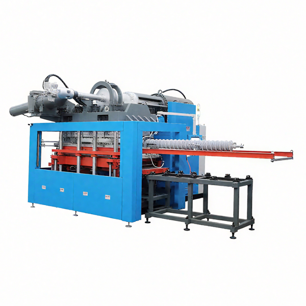
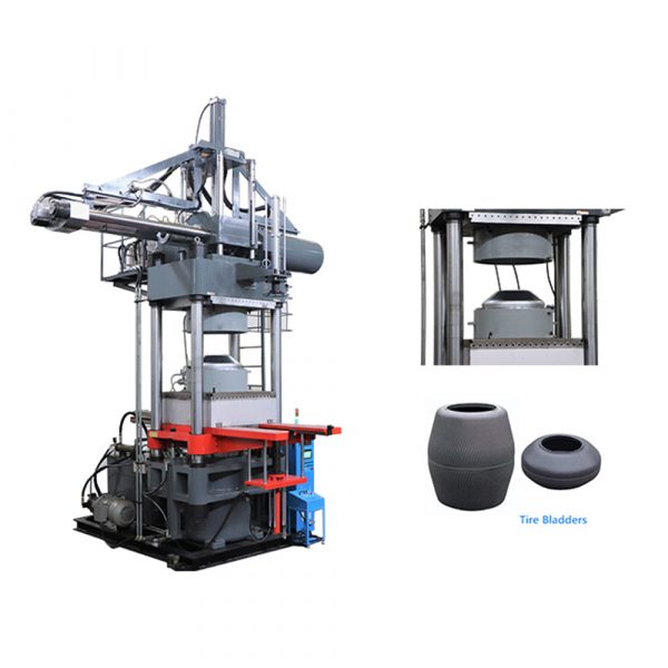
Excess flash remains a persistent waste stream on production floors: thin burrs around molded parts that force rework or rejection. The immediate technical levers are compound flow and injection velocity, so machines and process engineers lean on precise hardware—often a rubber injection molding machine—to stabilize performance. This piece follows a problem-driven logic: identify where flashes form, why they persist, and what manufacturing partners must change to cut scrap without compromising cycle time or compound properties.
Where and why flash starts
Flash forms when pressurized rubber escapes past tool clearances during mold fill or during cure when dimensional shifts occur. Root causes are usually a mix of mechanical and material factors: insufficient clamp force, errant shot size, rapid injection velocity spikes, worn parting lines, and inadequate mold venting. Compound behavior—viscosity and cure kinetics—interacts with these variables, so a stable injection profile alone can’t solve every case. Expect to see flash concentrate at gates and thin sections where flow fronts meet and pressure spikes.
Manufacturers’ role: machine design and tooling discipline
Rubber processing machinery manufacturers shape outcomes by offering tighter hydraulic control, programmable multi-stage injection, and improved platen alignment. Toolmakers contribute through precision parting lines, optimized gate design, and dedicated venting channels. Real-world anchor: tier-1 automotive suppliers around Detroit reported measurable reductions in visible flash after adopting machines with closed-loop velocity control and revising gate geometries—showing that equipment and tooling changes work together. Integration with reliable rubber molding equipment and scheduled maintenance is essential to maintain those gains.
Practical controls that cut flash without slowing production
Start by stabilizing the injection velocity profile: use a controlled ramp rather than abrupt full-speed fills. Match shot size to cavity volume plus a minimal cushion; excess overfill invites flash. Increase clamp force just enough to prevent parting-line separation, and tune backpressure to improve melt homogeneity. Thermal control matters—maintain consistent mold temperatures to avoid differential shrinkage. Also, inspect and maintain parting surfaces; a 0.1 mm gap is enough to leak compound. Use multi-stage injection to prioritize gentle flow through thin sections and higher pressure only when needed.
Common mistakes that negate equipment advantages
Teams often assume a high-performance machine eliminates the need for routine checks. That’s wrong. Typical errors: leaving shot size unrealistically high for safety margin, ignoring worn ejectors that change seating, and using injection velocity set to max because cycle time matters. Another frequent misstep is under-venting complex cavities; lack of escape path for air forces compound into gaps. Such operational oversights turn sophisticated controllers into cosmetic improvements rather than game changers.
Implementing a repeatable deflash framework
Build a short checklist that becomes standard operating practice: document optimal injection velocity curves per mold, record shot size baselines, log clamp pressures, and schedule tooling inspections. Combine statistical process control on flash thickness with periodic material verification (compound viscosity and cure state). Training is part of the framework—operators should recognize early signs of gating wear or rising backpressure. Small feedback loops matter: a weekly check prevents a monthly scrap spike.
Advisory: three golden rules to evaluate solutions
1) Measure directly: prioritize reduction in flash area per part and reject rate over cycle-time bragging. Use simple gauges or vision systems for consistent data. 2) Validate control strategy: require machines to demonstrate repeatable injection velocity profiles and closed-loop pressure control before committing to production. 3) Inspect tooling under load: evaluate parting-line behavior at operating clamp force to reveal real gaps rather than relying on static measurements.
These rules lead to clear outcomes: fewer rejects, predictable cycles, and lower manual finishing. The value becomes obvious when a process that once tolerated frequent rework runs cleanly under an aligned combination of equipment, tooling, and operator discipline—something HWAYI understands from machine-level controls and long-term service experience. HWAYI.
—